Why pressure losses matter in energy and water systems?
Water channels and ducts are key components in energy systems, cooling applications, and water distribution networks (White & Xue, 2021). Pressure losses in these systems directly affect pumping power requirements, operational costs, and overall efficiency. Every time water flows through a channel, friction consumes energy. These cumulative losses significantly affect system performance.
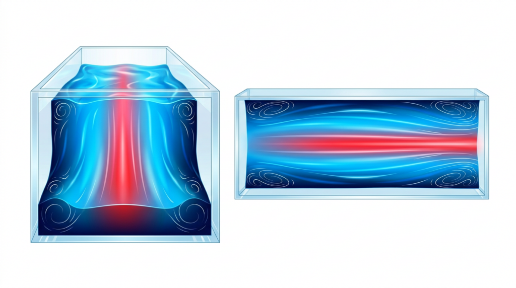
Circular pipes are often used as a reference in design calculations. They are simple, symmetric, and well understood. However, rectangular channels are common in practice, especially in cooling channels, laboratory systems, and compact installations. For example, air ducts in buildings or cooling channels inside electronic devices. Rectangular shapes are often preferred in space-constrained designs.
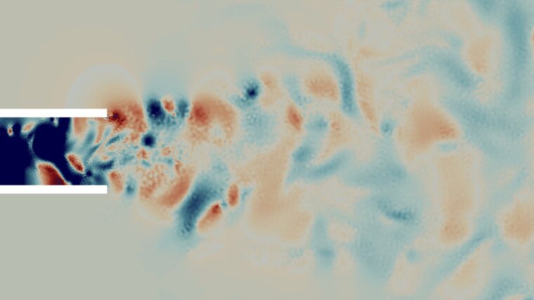
Unlike circular pipes, rectangular ducts have non-uniform velocity and increased friction due to sharp corners (Jones, 1976). Velocity is highest in the channel core and decreases near the walls and corners. This uneven flow creates small swirls known as secondary flows, which increase wall shear stress and energy dissipation.
As a result, Computational Fluid Dynamics (CFD) provides a valuable tool for investigating how flow behaviour and pressure losses depend on channel shape (Versteeg & Malalasekera, 2007). CFD allows engineers to see inside the channel, which analytical equations cannot capture.
Theoretical background
Pressure losses in pipes and channels occur due to viscous friction at the walls. The faster the water moves, the greater the friction it creates. The Darcy-Weisbach equation is the standard formula engineers use to calculate these losses (Brown, 2002).
For non-circular ducts, such as rectangular channels, engineers use a special value called the “hydraulic diameter” to adapt the circular pipe formula (Bejan, 2013). This approach provides reasonable accuracy for simple cases.
However, rectangular ducts introduce additional complexity. When water flows through a rectangular channel, sharp corners create small swirls known as secondary flows (Jones, 1976). These swirls increase friction and waste energy. The more elongated the rectangle, the stronger these swirls become.
CFD approach and modelling choices
The simulations were performed using ANSYS Fluent, applying a steady-state Reynolds-Averaged Navier-Stokes (RANS) approach. Water at 20 °C was used as the working fluid, and all walls were assumed to be smooth.
A two-dimensional fully developed flow model was used. While 3D simulations capture more detail, a 2D approach provides reasonably accurate predictions of pressure loss for fully developed flow in straight ducts, although it cannot capture all three-dimensional secondary flow structures.
The SST k–ω turbulence model was selected due to its strong performance in wall-bounded turbulent flows (Menter, 1994). Mesh refinement was applied near the walls, and a mesh independence study confirmed that the results were not sensitive to grid resolution. Both channel geometries were simulated at a Reynolds number of 30,000, representing fully turbulent flow. The inlet velocity was calculated based on the hydraulic diameter, and a pressure outlet boundary condition was applied at the channel exit.
To ensure reliable results, a sufficiently long channel was used to achieve fully developed flow. Convergence was tracked through both residual behaviour and the stability of the flow field, and pressure drops were determined using area-weighted averages at the inlet and outlet.
Geometry matters: Pressure loss and friction analysis
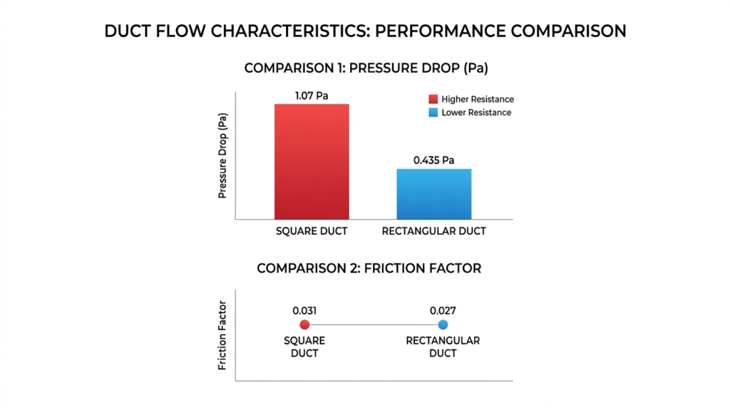
The simulations confirmed fully developed flow conditions for both geometries, with uniform velocity distribution along the channel length. However, clear differences in pressure losses and friction factors were observed. The square duct exhibited a significantly higher pressure drop (1.07 Pa) compared to the rectangular duct (0.435 Pa) despite having the same hydraulic diameter and Reynolds number (see Table 1). This demonstrates that channel geometry influences flow resistance even when the hydraulic diameter is kept constant.
The CFD-predicted friction factors were 0.031 for the square duct and 0.027 for the rectangular duct, both within ±10% of analytical values. This confirms the reliability of the CFD model while also highlighting limitations of analytical approaches, which cannot fully account for geometry-related effects such as secondary flows. The square duct (1:1) has four sharp corners that generate stronger secondary flows, increasing wall shear stress and energy loss. In contrast, the rectangular duct (4:1) experiences weaker secondary flows, resulting in lower friction and pressure drop.
CFD therefore provides added value by offering spatially resolved insights into velocity and pressure distributions, improving confidence in design decisions involving non-circular ducts.
| Geometry | Aspect Ratio | Pressure Drop (Pa) |
|---|---|---|
| Square duct | 1:1 | 1.07 |
| Rectangular duct | 4:1 | 0.435 |
How accurate is the CFD model?
To ensure the results were reliable, the CFD predictions were validated against both analytical correlations and experimental data. The square duct friction factor (0.031) compared well with the Blasius correlation (0.029) and experimental measurements (0.030–0.032) from Hartnett, Koh and McComas (1962). The rectangular duct friction factor (0.027) agreed with the Jones correlation (0.028) and experimental data (0.026–0.029) from Jones (1976). Overall, the CFD predictions were within ±10% of reference values, confirming the model’s accuracy.
Practical implications and future work
For engineers working with rectangular channels, this study shows that geometry has a measurable influence on pressure losses, hydraulic diameter estimates provide useful but simplified predictions, and CFD offers a powerful way to evaluate flow resistance in non-standard geometries. These findings are especially important in energy systems, where accurate pressure loss assessment supports efficient pump selection and overall system optimisation.
The study was intentionally limited in scope to suit a bachelor’s thesis, relying on a two-dimensional model, assuming smooth walls, using a single Reynolds number (approximately 30,000), and applying steady-state turbulence modelling. Future work could expand the analysis with three-dimensional simulations to capture secondary flow structures, incorporate surface roughness to better represent real engineering conditions, or explore a broader range of flow conditions to provide a more comprehensive understanding of the system.
Conclusion
This study confirms that CFD can reliably predict pressure losses in rectangular water channels under simplified conditions. Channel shape plays a significant role in determining flow resistance, and numerical modelling provides valuable insights beyond traditional analytical methods. By combining CFD with classical theory, engineers can achieve more accurate and informed design solutions in energy and hydraulic applications.
This article is based on the thesis work done by Mitu Mollah and supervised by Dr. Elena Kuisma. The thesis is available at https://urn.fi/URN:NBN:fi:amk-2026053119659.